Queen's Hyperloop Design Team 2025 to 2026

Pneumatic Braking System

A spring-applied, air-released braking system for a 200 kg Hyperloop pod.

Project description

Challenge
Design a brake for a 200 kg pod travelling at up to 35 m/s that can stop within 15 m
What I did
On the 2025–26 braking subteam, I worked on the overall braking system architecture and supported analysis, testing, and final assembly.
Current state
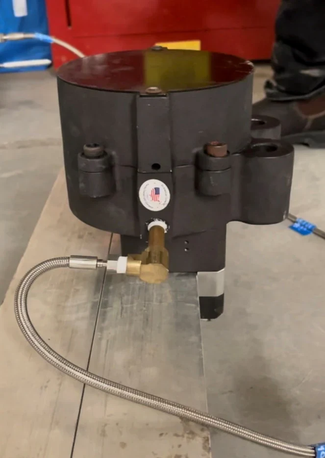
After depressurization, the caliper activated and clamped to the replica test track. Dynamic stopping remains untested.
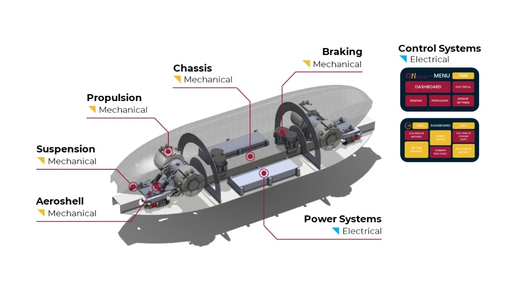
Labeled CAD diagram of the full hyperloop pod showing the aeroshell, suspension, propulsion, chassis, braking, power systems, control systems, and dashboard interfaces
Full pod layout with the braking system below the chassis

How it works

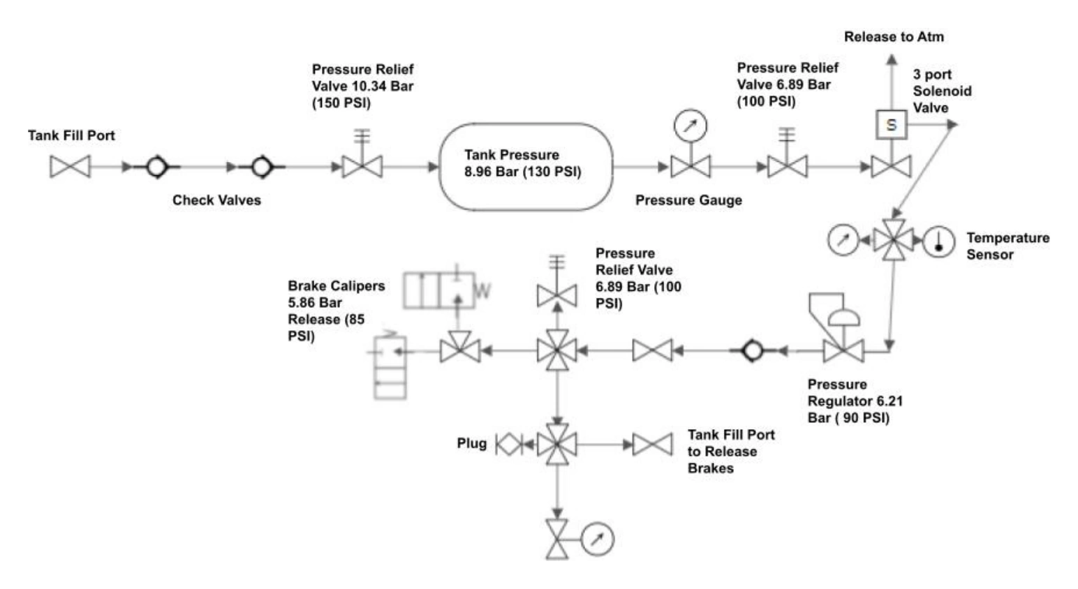
Team pneumatic schematic showing a 130 psi receiver, check valves, pressure relief, a three-port solenoid valve, a 90 psi regulator, and an 85 psi caliper release threshold
Fig. 1 — Full braking system schematic
  1. Fill

    The compressor fills the receiver to 130 psi.

  2. Release

    The regulator supplies about 100 psi; above 85 psi, the calipers stay open.

  3. Vent

    A brake command or loss of pod power vents the circuit through the solenoid.

  4. Clamp

    Below 85 psi, the springs close the calipers around the track.

Stopping distance

Estimating whether the pod would stop inside the braking zone.
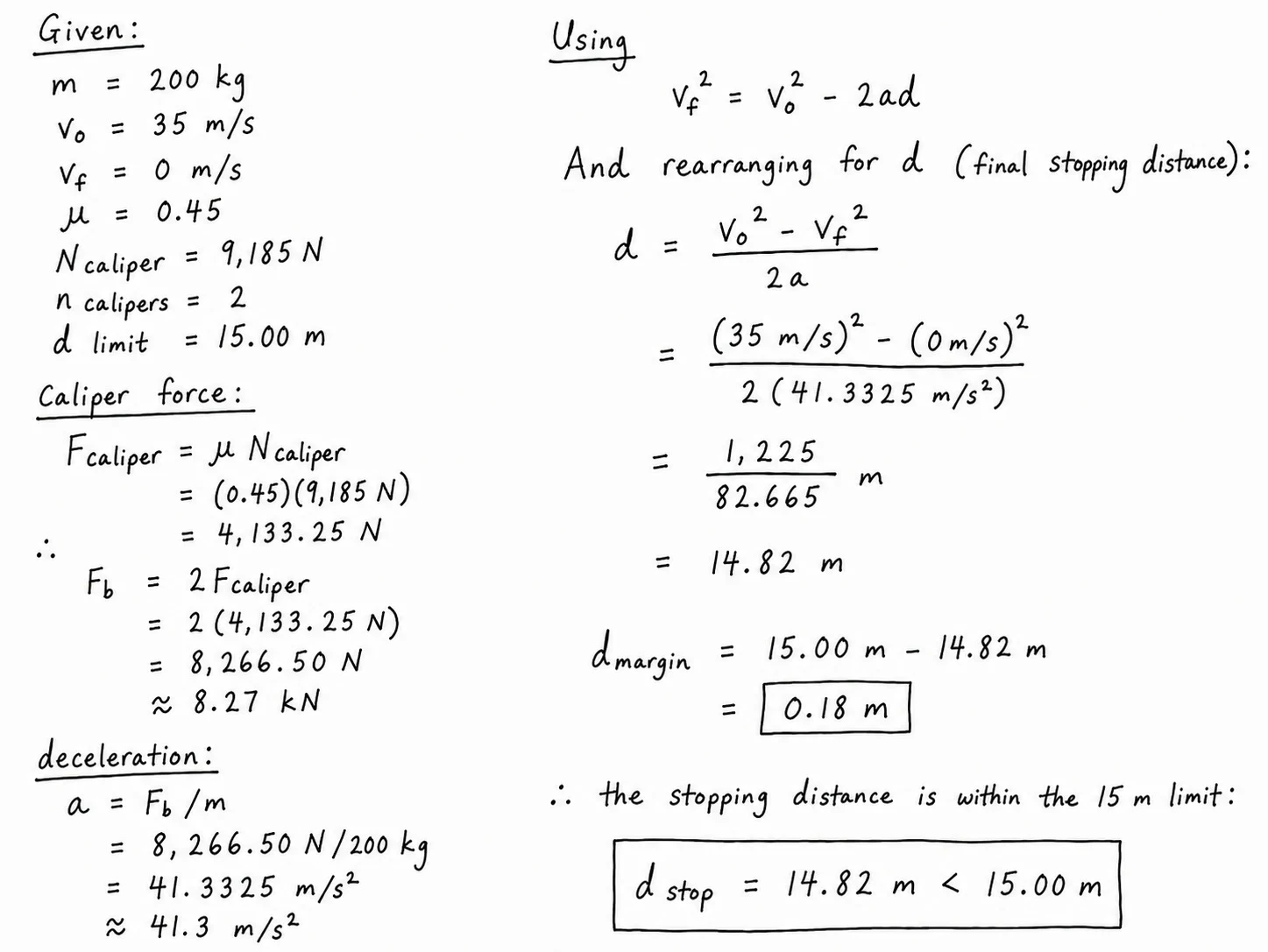
Handwritten stopping-distance calculation showing two calipers produce 8.27 kilonewtons of braking force, a 41.3 metres-per-second-squared deceleration, and a 14.82 metre stopping distance within the 15 metre limit

Caliper mount and fit check

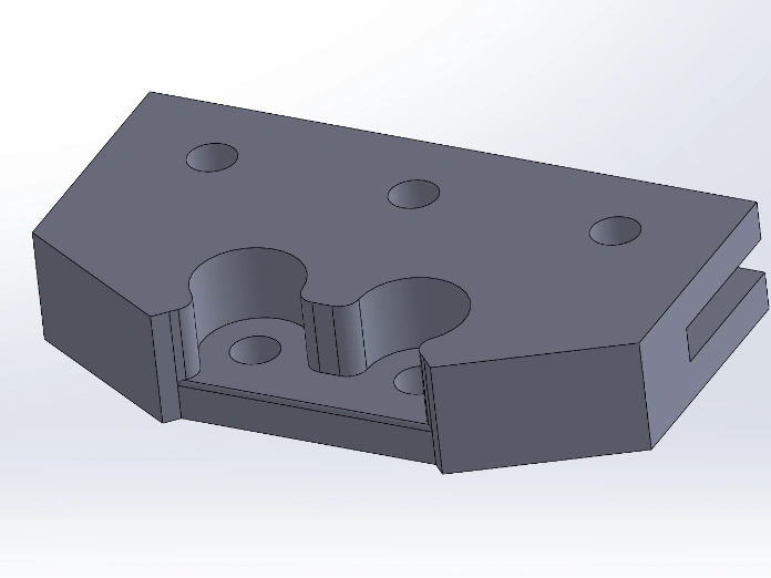
SolidWorks model of the custom Hyperloop brake caliper mount
Fig. 2 — CAD model of the caliper mount
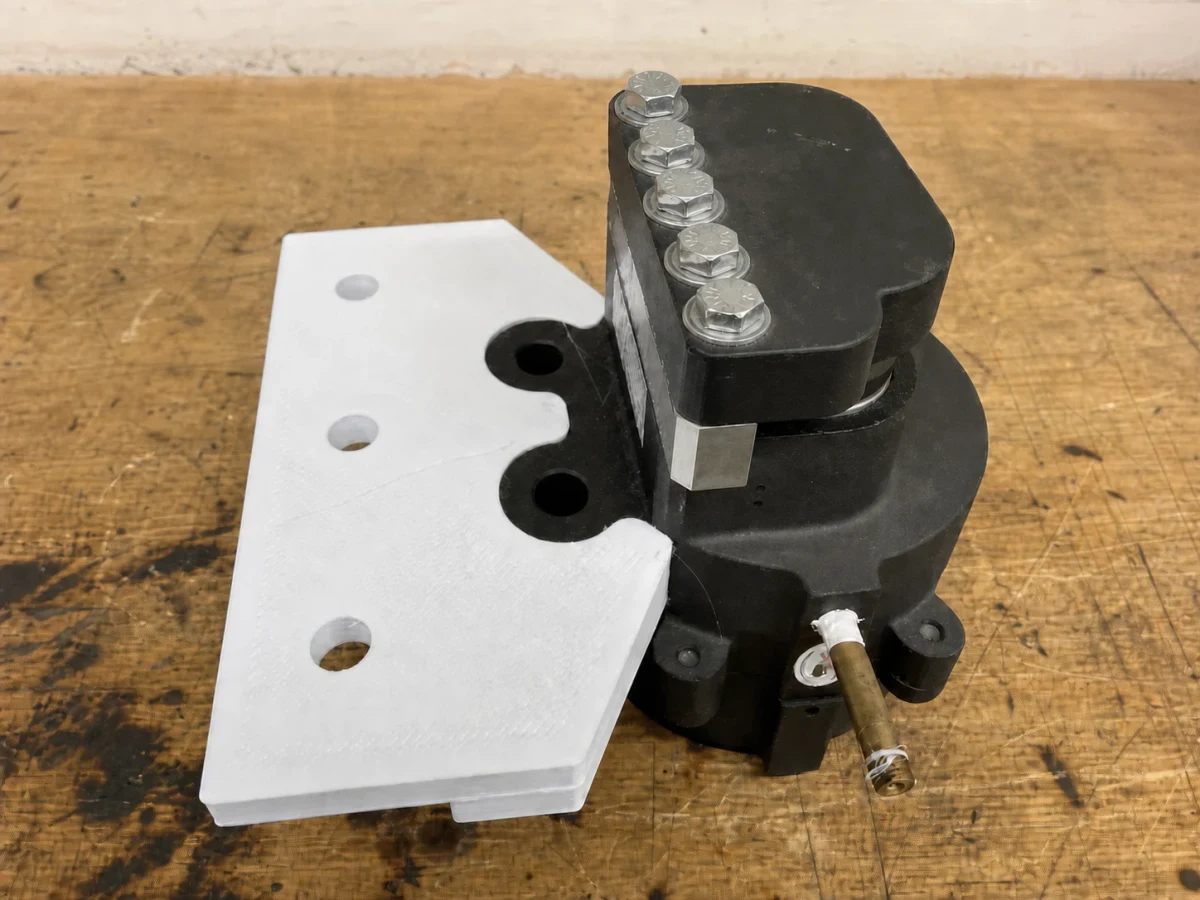
White full-scale printed mount positioned against the black pneumatic brake caliper
Fig. 3 — Full-scale printed mount fitted against the brake caliper

Mount and chassis load paths

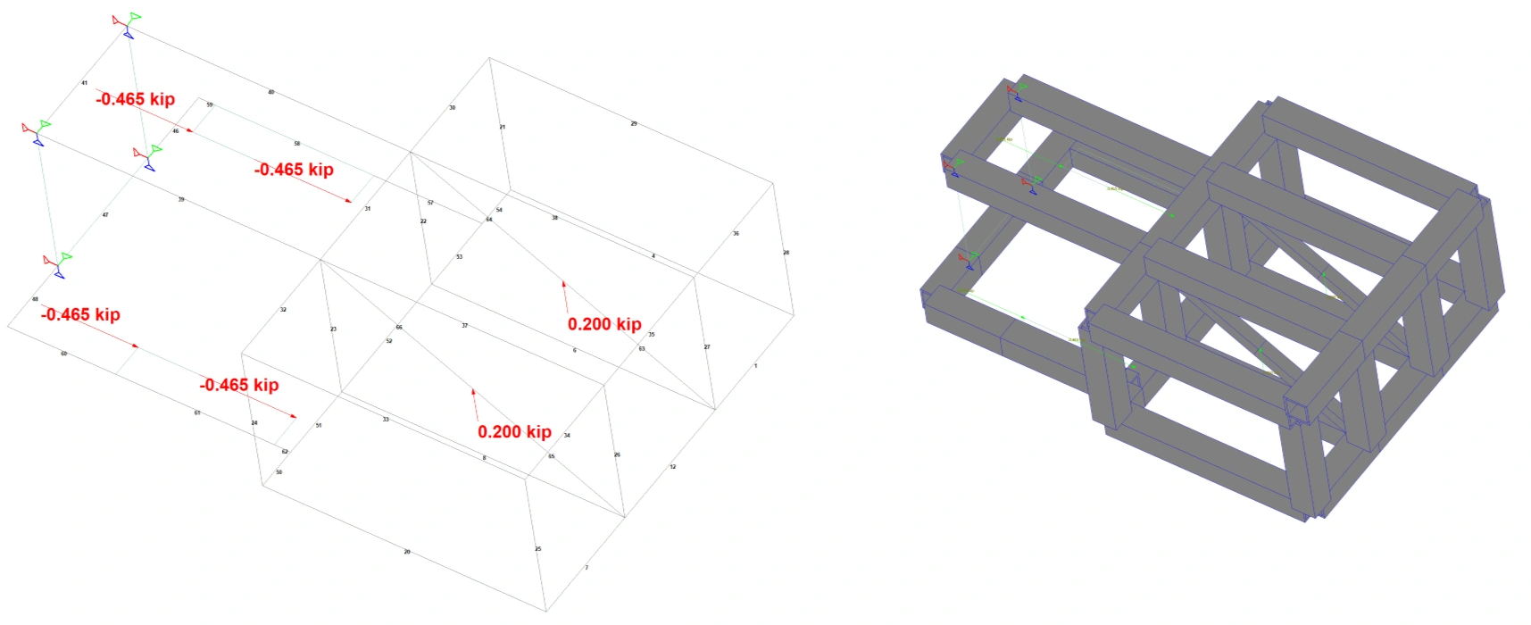
The team used SOLIDWORKS FEA to study the 4,133.25 N mount load and the braking load path through the chassis.
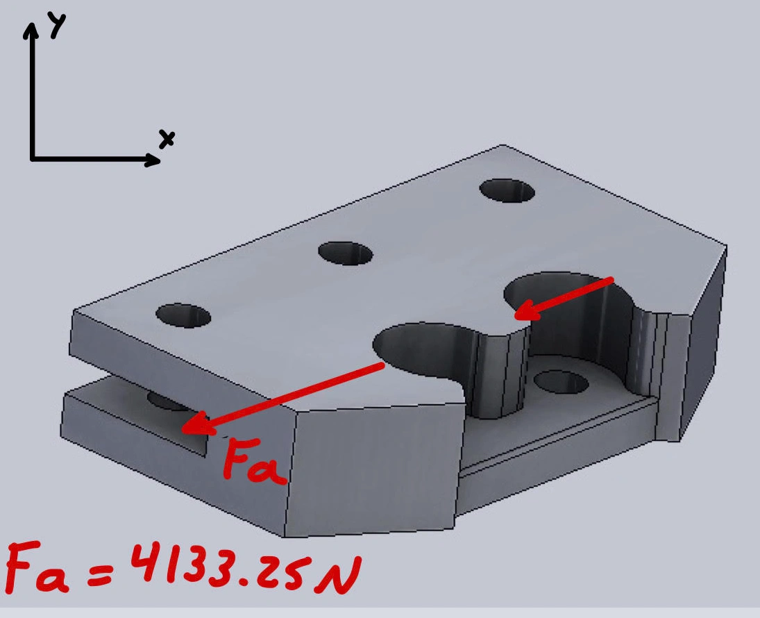
Brake mount diagram showing the direction of the caliper load
Fig. 4 — Caliper mount with the 4,133.25 N braking load marked in red
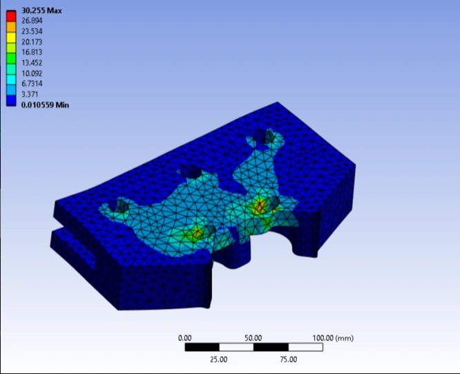
Finite element mesh and result contour for the brake caliper mount
Fig. 5 — FEA mesh and result contour from the team's analysis
Hyperloop chassis braking load case with four brake mount loads and support reactions at the upper wheels
Fig. 6 — Four −0.465 kip (≈−2,068 N) brake-mount loads and two 0.200 kip (≈890 N) upper-wheel reactions

Brake clamp test

Pneumatic brake caliper clamped around a replica I-beam after the circuit was depressurized
Fig. 7 — Caliper clamped around a replica I-beam after the circuit was depressurized